VS: Raspberry Pi Zero W und Sensoren: Unterschied zwischen den Versionen
Geli (Diskussion | Beiträge) Keine Bearbeitungszusammenfassung |
Geli (Diskussion | Beiträge) Keine Bearbeitungszusammenfassung |
||
| Zeile 22: | Zeile 22: | ||
Da der Sensor über eine fixe Adresse auf dem I2C-Bus verfügt, ist für den Anschluss eines weiteren Sensors noch folgende Ergänzung notwendig (Zitat aus dem Datenblatt): | Da der Sensor über eine fixe Adresse auf dem I2C-Bus verfügt, ist für den Anschluss eines weiteren Sensors noch folgende Ergänzung notwendig (Zitat aus dem Datenblatt): | ||
* The SHT31 has a default I2C address of 0x44 which can also be changed to 0x45 by connecting the ADR pin to the VIN pin to pull the ADR pin high. So, connect the ADR pin to the 5V pin on the Arduino and also modify the sketch so that when creating the SHT31 object, the address 0x45 can be defined. | * The SHT31 has a default I2C address of 0x44 which can also be changed to 0x45 by connecting the ADR pin to the VIN pin to pull the ADR pin high. So, connect the ADR pin to the 5V pin on the Arduino and also modify the sketch so that when creating the SHT31 object, the address 0x45 can be defined. | ||
==Test== | |||
Ist der Sensor auf einem Breadboard geeignet verkabelt, kann mit folgendem Pythonprogramm ein erster Test versucht werden: | |||
#!/usr/bin/env python | |||
# -*- coding: utf-8 -*- | |||
# Read SHT31 | |||
#-------------------------------- | |||
import os, sys, time | |||
import smbus | |||
# Get I2C bus | |||
bus = smbus.SMBus(1) | |||
# SHT31 address, 0x44(68) | |||
bus.write_i2c_block_data(0x44, 0x2C, [0x06]) | |||
time.sleep(0.5) | |||
# SHT31 address, 0x44(68) | |||
# Read data back from 0x00(00), 6 bytes | |||
# Temp MSB, Temp LSB, Temp CRC, Humididty MSB, Humidity LSB, Humidity CRC | |||
data = bus.read_i2c_block_data(0x44, 0x00, 6) | |||
# Convert the data | |||
temp = data[0] * 256 + data[1] | |||
cTemp = -45 + (175 * temp / 65535.0) | |||
fTemp = -49 + (315 * temp / 65535.0) | |||
humidity = 100 * (data[3] * 256 + data[4]) / 65535.0 | |||
# Output data to screen | |||
print "Temperature in Celsius: %.2f C" %cTemp | |||
#print "Temperature in Fahrenheit: %.2f F" %fTemp | |||
print "Relative Humidity: %.2f %%RH" %humidity | |||
Version vom 22. Januar 2019, 19:43 Uhr
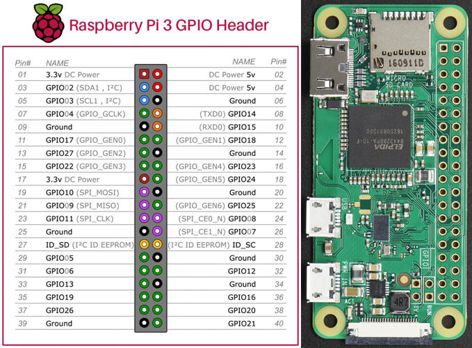
Wegen der geringen Workload des Projektes - Sensoren auslesen, kleine Berechnungen - wird ein Raspberry Zero W eingesetzt, der für sich einen Stromverbrauch vom ca. 1 W aufweist. Er hat, wie alle neueren Raspis einen 40-poligen Anschlusskonnektor.
https://de.pinout.xyz/#
Der Rechner verfügt über WLAN und kann damit ins Netzwerk eingebunden werden.
Betriebssystem: Raspbian Stretch Lite
Die gesamte root-Partition wird auf einen 16GB USB-Stick verschoben, sodass die SD-Karte nur beim Bootvorgang kurz lesend angesprochen wird. Eine eigene Datenpartition wird nicht benötigt, da nur Messwerte gespeichert werden. Siehe Root-Filesystem auf USB-Datenträger umstellen.

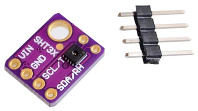
SHT31-D Temperature and Humidity Sensor
Für die Ventilatorsteuerung werden 2 Sensoren des Typs SHT31-D verwendet. Diese Sensoren liefern eine hohe Genauigkeit und arbeiten in einem weiten Temperaturbereich.

Auszug aus dem Datenblatt:
RH (Relative Humidity) operating range: 0 - 100% RH
Temperature range: -40 to +125°C
Typical Humidity accuracy: +/- 2%
Typical Temperature accuracy: +/- 0.2°C
I2C Interface with two user selectable addresses
Der Anschluss an den Raspberry Pi entspricht dem Luftdrucksensor BMP180, der ebenfalls über den I2C-Bus arbeitet - jedenfalls bis zum Punkt Software installieren. Funktioniert der Sensor nicht auf Anhieb, ist http://www.netzmafia.de/skripten/hardware/RasPi/RasPi_I2C.html eine gute Einstiegsseite für die Problemsuche.
Da der Sensor über eine fixe Adresse auf dem I2C-Bus verfügt, ist für den Anschluss eines weiteren Sensors noch folgende Ergänzung notwendig (Zitat aus dem Datenblatt):
- The SHT31 has a default I2C address of 0x44 which can also be changed to 0x45 by connecting the ADR pin to the VIN pin to pull the ADR pin high. So, connect the ADR pin to the 5V pin on the Arduino and also modify the sketch so that when creating the SHT31 object, the address 0x45 can be defined.
Test
Ist der Sensor auf einem Breadboard geeignet verkabelt, kann mit folgendem Pythonprogramm ein erster Test versucht werden:
#!/usr/bin/env python
# -*- coding: utf-8 -*-
# Read SHT31
#--------------------------------
import os, sys, time
import smbus
# Get I2C bus
bus = smbus.SMBus(1)

# SHT31 address, 0x44(68)
bus.write_i2c_block_data(0x44, 0x2C, [0x06])

time.sleep(0.5)

# SHT31 address, 0x44(68)
# Read data back from 0x00(00), 6 bytes
# Temp MSB, Temp LSB, Temp CRC, Humididty MSB, Humidity LSB, Humidity CRC
data = bus.read_i2c_block_data(0x44, 0x00, 6)

# Convert the data
temp = data[0] * 256 + data[1]
cTemp = -45 + (175 * temp / 65535.0)
fTemp = -49 + (315 * temp / 65535.0)
humidity = 100 * (data[3] * 256 + data[4]) / 65535.0

# Output data to screen
print "Temperature in Celsius: %.2f C" %cTemp
#print "Temperature in Fahrenheit: %.2f F" %fTemp
print "Relative Humidity: %.2f %%RH" %humidity